Modern isokinetics machines use several components to create isokinetic resistance.
Apart from the base of the machine and chair/bed to perform tests/exercises from the main component of the modern isokinetic machine is the dynamometer.
This is the part of the machine that does all of the work and is by far the most expensive piece. It is made up of many different parts:
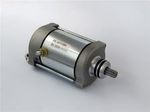
Motor:
A motor is used to generate the resistance to movement (or to create movement in some machines e.g. constant passive motion or CPM for short). This motor may be a direct current (DC) or alternating current (AC) unit. AC units have only just become capable of generating the resistance needed and so are fitted to fewer devices. The more common motor is the DC version.
DC Motors:
Brushed:A DC motor with brushes generates torque directly using electricity (in this case direct current hence the name), Inside there are electrical magnets which can be stationary or rotating. They work on the principle of Lorentz force, a current carrying conductor is placed within the magnetic field and is subjected to torque (turning force) known as Lorentz force. Brushed DC motors are cheap and highly reliable. They offer easy control of speed and motion, however, they are costly to maintain needing regular cleaning and offer low life spans.
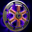
Brush-less: DC motors without brushes use a rotating permanent magnet, with stationary electrical magnets on the outside. They can not be run directly with DC power so the power is converted to a type of alternating current (AC). They are much more simple than brushed motors and offer life span, little or no maintenance, and high efficiency. They are however, much more expensive and require more complicated motor speed controllers.
AC Motors:
Running on alternating current (the same that comes from your wall outlet) an AC motor consists of two parts, an outside stationary stator (usually copper coils) which produce a rotating magnetic field when AC current is applied, and an inside rotor attached to the output shaft that is drive (torque is produced) by the rotating field. There are two types of AC motors. The first is the synchronous motor, the second type is the induction motor. AC motors are reliable and requires little maintenance. They are, however, larger and heavier than DC motors and require a good power supply to generate allot of torque.

Regardless of the type of motor used a system is required to transfer the torque. Normally a gearbox is used for this purpose (some AC motors are so powerful they do not require a gearbox). normally isokinetics devices employ a single gear that does not require a clutch system (older systems used a clutch to create the isokinetic force).
Not all motors are created equally. Earlier motors had a decreased torque level at higher speeds. This meant that a claimed torque of 500nm at 100 degrees per second could be as little as 100nm at 500 degrees per second. This torque slope ‘drop off’ meant earlier machines were much less reliable at higher speeds. Modern machines do not suffer from this ‘drop off’ as much. This is partly because the manufacturers have kept the top speed constant at 500 degrees per second whilst incrementally increasing the torque available at higher speed and limiting the torque available at lower speeds. This has all helped reliability and increased the ability of the machines to perform at high speeds.
Control System:
A mechanism is then required to control the speed and force of the motor so it matches the input. This is normally achieved through a servomechanism, or servo. This uses error-sensing negative feedback to correct the performance of the motor. This controler uses a closed loop feedback, which looks at the speed and adjusts the torque applied to keep the speed constant. Servos operate on the principle of negative feedback, where the control speed is compared to the actual speed of the mechanical system as measured a spedd transducer at the output. Any difference between the actual and wanted speed is amplified and used to provide electricity to the motor to drive the shaft in the direction necessary to eliminate the error.
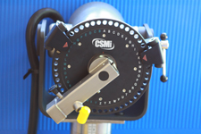
Sensors:
Force Sensors are then used to work out how much force is being applied to the shaft from the motor. This helps in controlling various modes of resistance but is really employed to get feedback on performance from the external input (usually a person attached to the machine for exercise or testing). On early models the force sensor was a simple transducer called a load cell.
A load cell is a transducer it is used to convert a force into electrical signal. Pressure deforms the gauge (usually crystal based). The gauge then converts the deformation (strain) to electrical signals which have to be interpreted by a computer. Load cells are subject to ‘ringing’ when force direction is altered abruptly (as it nearly always is in isokinetics) they are also very delicate and can be easily damaged or simply un-calibrated. The distance of the load cell from the axis of rotation is crucial this often then requires manual input of the length of the lever arm for them to work. For these reasons they are not seen in modern systems.
The more comman way of measuring force is to use a Conventional Rotary Torque Transducers with a rotary shaft and static body. This torque sensor transmits the torque signal from the rotating shaft within the transducer body. The static element of the torque sensor is mounted to the rotary shaft (the center of rotation of the input mount) a strain gauge is included on the assembly giving accurate and reliable torque measurement. It has a central element and on-shaft rotating conditioning electronics. Signals are transmitted to the non-rotating part of the system or stator. This gives a torque value. Higher end systems use 2 of these sensors to give reliability and decrease the need for calibration. In fact the amount of ‘creep’ (the amount of error or drift between calibrations) is often less than 0.1%.
A position sensor is also incorporated to allow accurate determination of position for interpretation and setting up of positions along with functioning in certain motions e.g. isometric. A rotary encoder, also called a shaft encoder, is normally used these are an electro-mechanical device that converts the angular position of a shaft or axle to an analog or digital code, making it an angle transducer. Higher end machines often have 2 of these sensors.

Input Adaptor:
All machines then have some way of attaching ‘tools’ to the shaft to allow force input from an external source (normally a limb or body segment) this input may be an ‘arm’ or a shaft to clip items to or a hole to attach items onto. In all situations these need to be robust enough to take the force applied to them. In essence the bigger the attachment the stronger the connection and hence the more force can be taken.
Dynamometer mount:
The dynamometer is mounted onto a base to give stability during tests or exercises. This mount may be stationary (as in the Con-Trex leg press) or movable around an axis with height adjustment (as on the Norm or System 4) It may even be mounted to a height column (as in the Con-Trex or BTE systems). The key is how stable the unit is. The greater the stability the better for testing / exercising.
Chair:
For testing isolated joints and many combination movements a chair and or table is required to stabilise the subject. The size and stability of the chair are key. The larger and more stable the chair the better as this will prevent un-necessary movement which would limit the validity of the results. A chair attached to the base of the machine offers the best stability. Generally the chair on modern systems will lay flat to allow both a chair and table in a single unit. This is by far the best solution. All chairs offer straps and stabilisers to improve control.
Computer system:
Modern dynamometers are very powerful. In fact they are too powerful to allow full manual control. This means they are all driven by computer systems to give increased safety and system stability. Computer change quickly so it is important that the system can be upgraded to the latest technology. If it can’t it will become a very expensive ornament!